Choosing The Right Additive Manufacturing Process for Your Project
Everyone from the garage hobbyist to multi-functional engineering and manufacturing teams at Fortune 100 companies can benefit from the flexibility and rapid turnaround offered by additive manufacturing. The options for additive manufacturing, commonly referred to as 3D printing, include a whole host of technologies. For someone considering additive manufacturing for a project, the choices of technology might feel like a jumble of technical jargon that can make even the most adept designer reach for more familiar traditional manufacturing processes.
To make sense of the many additive manufacturing processes available, we will break down six major technologies: Fused Deposition Modeling (FDM), Stereolithography (SLA), Selective Laser Sintering (SLS), HP Multi Jet Fusion (MJF) 3D Printing, PolyJet 3D, and Direct Metal Laser Sintering (DMLS). Each of these technologies is offered at Xometry and has various capabilities and design limitations.
Fused Deposition Modeling (FDM)
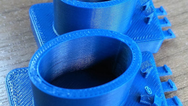
Fused Deposition Modeling is a common type of additive manufacturing. It is a material extrusion technology because it uses a continuous filament from a spool to build parts. The filament is fed through a heated extrusion head and deposits thermoplastic polymer material in successive layers to build up a 3D structure. The strength is limited by how well each layer is melted and bonded. The out-of-box surface finish shows the deposited layers.
In most cases, the layers can be sanded off in post-processing or a filler primer can be added to fill in surface blemishes. FDM can be a cost-effective plastic additive manufacturing technology when used for the right applications.
Limitations of Fused Deposition Modeling
FDM parts can be prone to warping, especially in high performance materials such as Nylon and Ultem. FDM parts have a noticeable texture because of the nature of filament deposition combined with relatively coarse layer thickness (0.010” or 0.013”).
Xometry FDM Capabilities
- Materials: ABS, Polycarbonate, Nylon, and other high-performance plastics
- Maximum Part Size: 36″ x 24″ x 36″
- Tolerances: +/- 0.004” for the first inch, plus 0.002” per inch
- Layer thickness: 0.010” layers for parts less than 16” max dimension
- 0.013” layers for parts over 16” max dimension
- Lead Time: Starts at 3 business days
A custom manufactured FDM part
Stereolithography (SLA)
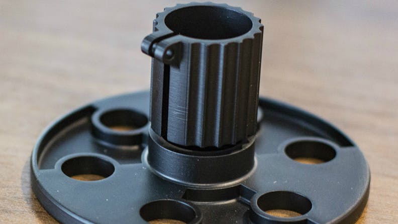
Stereolithography is a vat polymerization technology because it uses an ultraviolet (UV) laser to selectively cure sections of plastic inside of a pool of liquid thermoset polymer resin. The part is successively built up in layers as the cured sections move down and a new layer deposits onto the free surface. Out of box, an SLA part has limited strength. All SLA parts receive a final UV post-cure after build for improved mechanical properties. The polymerization process offers a superior surface finish over FDM. Enhanced thermal properties can be achieved, on some materials, when a thermal post-cure is performed after the UV post-cure.
Limitations of Stereolithography
SLA parts will have a limited life span. Exposure to UV light will cause SLA parts to darken and become more brittle with time. SLA parts may also absorb moisture and expand over time.
Xometry SLA Capabilities
- Materials: A selection industrial-grade thermoset plastics from DSM Somos and Accura (3D Systems)
- Maximum Part Size: 29″ x 25″ x 21″
- Tolerances: +/- 0.004” for the first inch, plus 0.001” per inch
- Layer thickness: 0.004” thick layers – standard resolution
- 0.002” thick layers – high resolution
- Lead Time: Starts at 4 business days
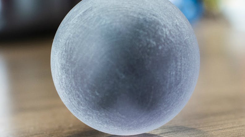
A custom manufactured SLA part
Selective Laser Sintering (SLS)
Selective laser sintering is a powder bed fusion technology. It is similar to SLA technology but uses a bed of thermoplastic polymer powder. In the case of SLS, a CO2 laser selectively sinters sections of the powder together to build a part up successively in layers. The sintered sections move down, and a new layer sinters to the free surface. Once an SLS part is cooled, depowdered, and grit-blasted, it is ready for use. SLS is often a cost-effective option for small production runs. The sintering process provides an excellent combination of mechanical strength, accuracy, and low-cost to make it one of the most versatile additive manufacturing processes.
Limitations of Selective Laser Sintering
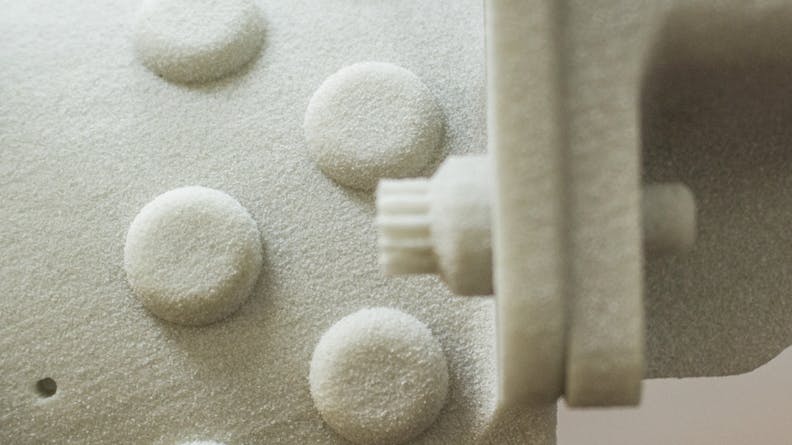
SLS parts may be porous and have a slightly grainy surface finish. Parts with thicker geometries, flat or broad parts, and parts with uneven wall thicknesses will be prone to significant deviations or warp due to variable thermal shrinkage and stress. Parts do not require a support structure, but escape holes are necessary to remove powder from any internal cavities.
Xometry SLS Capabilities
- Materials: Unfilled and glass-filled Nylon 12
- Maximum Part Size: 26″ x 15″ x 17″ for glass-filled Nylon 12
- Tolerances: +/- 0.005” for the first inch, plus 0.002” per inch
- Layer thickness: 0.004” thick layers
- Lead Time: starts at 3 business days
A custom manufactured SLS part
HP Multi Jet Fusion (MJF) 3D Printing
HP Multi Jet Fusion is a powder bed fusion technology. It is very similar to SLS technology, except an infrared (IR) light absorptive ink acts as a fusing agent and dispenses in regions where the material will be fused. An IR source creates fused sections and facilitates the fusion between layers. HP MJF parts build much faster in quantity than single point-based systems such as SLS or FDM for faster total processing time and shorter lead times. Mechanical properties are near isotropic.
Limitations
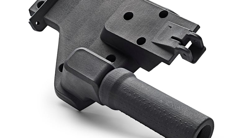
Like SLS, HP MJF parts have a grainy surface finish. Currently, the colors are limited to grey to black only. Otherwise, parts made through HP MJF have similar limitations as SLS.
Xometry HP Multi Jet Fusion Capabilities
- Materials: Unfilled and glass-filled Nylon 12
- Maximum Part Size: 15″ x 14″ x 11″
- Tolerances: +/- 0.012” for the first inch, plus 0.003” per inch
- Layer thickness: 0.0031” thick layers
- Lead Time: starts at 3 business days
A custom manufactured MJF part
PolyJet 3D
PolyJet 3D is a material jetting technology. As the name suggests, PolyJet functions like an inkjet printer. A printhead sprays droplets of liquid thermoset photopolymer to build up successive layers of material. Exposing the polymer to ultraviolet (UV) light cures it. Polyjet is precise and layers of dissimilar materials —such as a rubberized coating on a rigid base—can be deposited. Like SLA, fairly homogenous strength is possible. PolyJet allows for multi-material printing with a superior surface finish in either matte or gloss.
Limitations of PolyJet 3D
PolyJet materials are photopolymers, so they will darken with UV exposure. There are large PolyJet printers, but most are for small parts at a high quantity. This technology uses a dissolvable support material but requires a line of sight access to the supports, so they can be removed with a pressurized stream of solvent. They have limited mechanical properties and will degrade over time. PolyJet can be a relatively high-cost plastic additive process.
Xometry PolyJet Capabilities
- Materials: rigid and rubber-like photopolymers
- Maximum Part Size: 19″ x 15″ x 7″
- Tolerances: +/- 0.004” for the first inch, plus 0.001” per inch
- Layer thickness: .0018” thick layers
- Lead Time: starts at 1 business day
A custom manufactured PolyJet part
Direct Metal Laser Sintering (DMLS)
Direct Metal Laser Sintering is a powder bed fusion technology. It is similar to SLS technology except it uses granulated metal powder. In the case of DMLS, a high-power laser is used to melt powder successively in layers in an inert gas atmosphere to prevent oxidation. Once a DMLS part is cooled and cleaned, it is ready for use. The sintering process offers nearly isotropic mechanical properties and allows more areas of design freedom than traditionally manufactured metal parts.
Limitations
DMLS parts have a rough and grainy surface finish. Parts can warp, so orientation and support strategy during design and printing is critical. Unlike SLS, parts require support structure, so avoid hollow sections are not self-supporting. Although the cost is high relative to other metal manufacturing, DMLS is viable for small batch manufacturing.
Xometry DMLS Capabilities
- Materials: Aluminum and Steel
- Maximum Part Size: 9.5″ x 9.5″ x 12.5″
- Tolerances: +/- 0.005” for the first inch, plus 0.002” per inch
- Layer thickness: 30-40 microns
- Lead Time: Starts at 5 business days
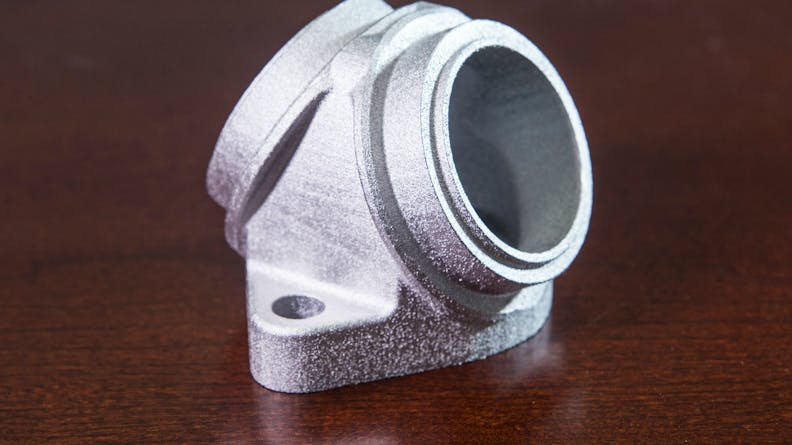
A custom manufactured DMLS part

